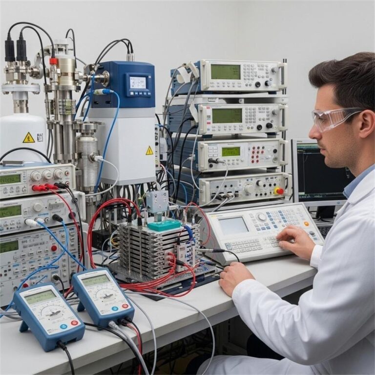
Specify a fuel cell test system’s hydrogen demand at the test inlet before selecting the PEM supply equipment. The generator’s rated output alone does not establish that it can meet the test sequence, gas-quality requirement or control interface. Coordinate the generator, test bench and site responsibilities.
This guide concerns research and test integration. It does not establish compatibility with a particular fuel cell or approve a complete hydrogen installation.
Cover illustration: conceptual scene; configuration varies by project.
1. Describe the test duty
Obtain the fuel-cell or test-bench supplier’s gas requirements. Record the fuel cell technology, inlet conditions, relevant impurity limits and permitted supply variation. Distinguish normal consumption from any start-up, purge or transient demand defined by the test procedure.
Provide the planned load sequence and operating schedule rather than only a maximum flow number. Identify whether the supply must continue through generator start-up, standby or a test interruption.
2. Agree the integration interfaces
| Interface | Information to agree | Responsible parties |
|---|---|---|
| Gas demand | Flow profile, peaks, duration and reference conditions | Test owner and supply-system engineer |
| Gas quality | Impurity limits, moisture, sampling point and evidence | Fuel-cell supplier, laboratory and equipment supplier |
| Pressure and conditioning | Required inlet conditions and any treatment or regulation | Test-bench supplier and system integrator |
| Buffering and continuity | Duty transitions and interruption requirements | Competent integration and safety team |
| Controls | Ready states, permissives, alarms, shutdown signals and data | Generator and test-bench control owners |
| Site services | Electrical supply, water, cooling and gas-handling arrangements | Facilities team and responsible installer |
| Acceptance | Test configuration, measurements, records and sign-off | All parties responsible for the combined system |
3. Separate equipment functions and boundaries
Identify which party supplies gas treatment, pressure regulation, any buffer equipment, flow control, valves and measurement equipment. Agree where performance is measured and who owns the connection to the test inlet.
Buffering, pressure arrangements and safety functions need design review for the actual demand and installation. They should not be selected from a generic capacity table without the responsible engineer’s assessment.
4. Coordinate controls and safety planning
Define the information exchanged between the supply equipment and the test bench. Agree how ready, running, standby, alarm and shutdown states are interpreted and which party implements each function.
Use the DOE hydrogen safety resources as context for organising the competent project review. This purchasing worksheet does not specify safety logic, vent design or operating procedures.
5. Test the agreed combined duty
Separate generator factory acceptance from verification of the connected test system. Define the relevant load sequence, sampling points, measurement methods, acceptance criteria and records. Review changes to gas conditioning, pressure controls or software before relying on earlier evidence.
For initial selection, review laboratory hydrogen supply equipment and PEM systems. Use the OEM RFQ checklist to communicate the integration scope.
Discuss hydrogen supply for your fuel cell test project
Send your institution or company, fuel-cell and test-bench identity, gas requirements, demand sequence, inlet pressure, utilities, control interfaces, destination and project schedule. Identify the equipment your team already supplies.
Published by Hele Titanium Hydrogen. Updated 17 October 2026. Product fit and combined-system performance require engineering review and agreed acceptance evidence.