
Home / Hydrogen Applications
Applications

Hydrogen Applications: Select by Duty, Not by Catalogue

Start with what the gas has to do — carrier, fuel, reaction gas or process feed — then with how much of it is needed at the same time. Flow, duty cycle, required gas quality and the delivery point decide the configuration. This page routes you to the application closest to your project.
0.5–200
Nm³/h system range
99.999%
Hydrogen purity
By model
Delivery pressure
PEM
Water electrolysis, deionised water
PEM water electrolyzer systems for on-site hydrogen production
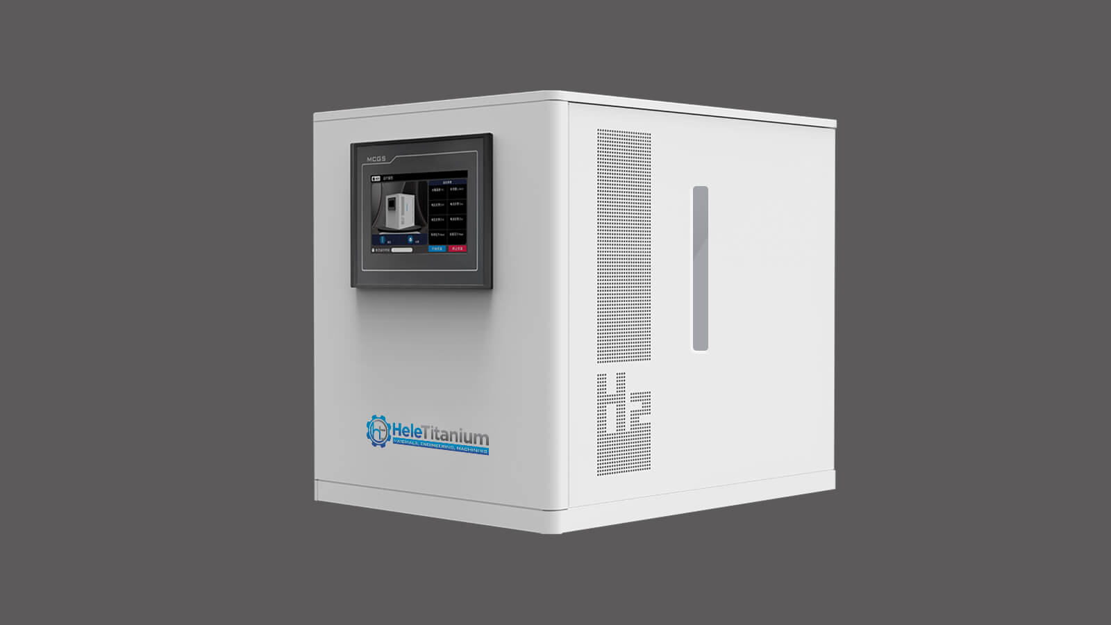
Reference configuration shown. Supplied equipment and appearance depend on the approved specification.
Project scope

Find the right equipment pathway

Compare PEM systems within the published 0.5–200 Nm³/h range. Laboratory instruments, OEM stacks and teaching equipment have separate product specifications; application demand is not a promise that every flow is a standard system size.
01 · Production gas
Start with simultaneous demand and operating hours.
02 · Laboratory
Check the instrument model and gas specification.
03 · OEM integration
Define who supplies power, water, cooling and controls.
04 · Teaching
Choose an educational kit by learning objectives, not plant output.
Purpose & value

Three questions decide the system before price is discussed

Most specification errors trace back to answering these three loosely. Answering them precisely is what makes the quotation comparable between suppliers.

01 · How much gas, at the same time?

Not the daily average. Concurrent peak demand across every consumer on the header sets the capacity, and it is the number most often underestimated.

02 · What quality, at the delivery point?

The receiving instrument or process sets the moisture and impurity limits. A headline purity percentage measured at the generator outlet does not answer this.

03 · What happens when it is serviced?

Availability is a design input, not a maintenance detail. Stating the target uptime determines whether redundancy belongs in the configuration.
Note on the figures on this page. Output, pressure and purity values describe reference ranges, not every simultaneous operating point. Final technical values, documentation and delivery terms belong in the approved quotation.
Applications

Where the system is used

Laboratory PEM hydrogen generator supplying analytical instruments

Laboratory & analytical

Carrier, detector fuel and reaction gas for GC, GC-MS and related instruments, specified against instrument compatibility and method requirements.
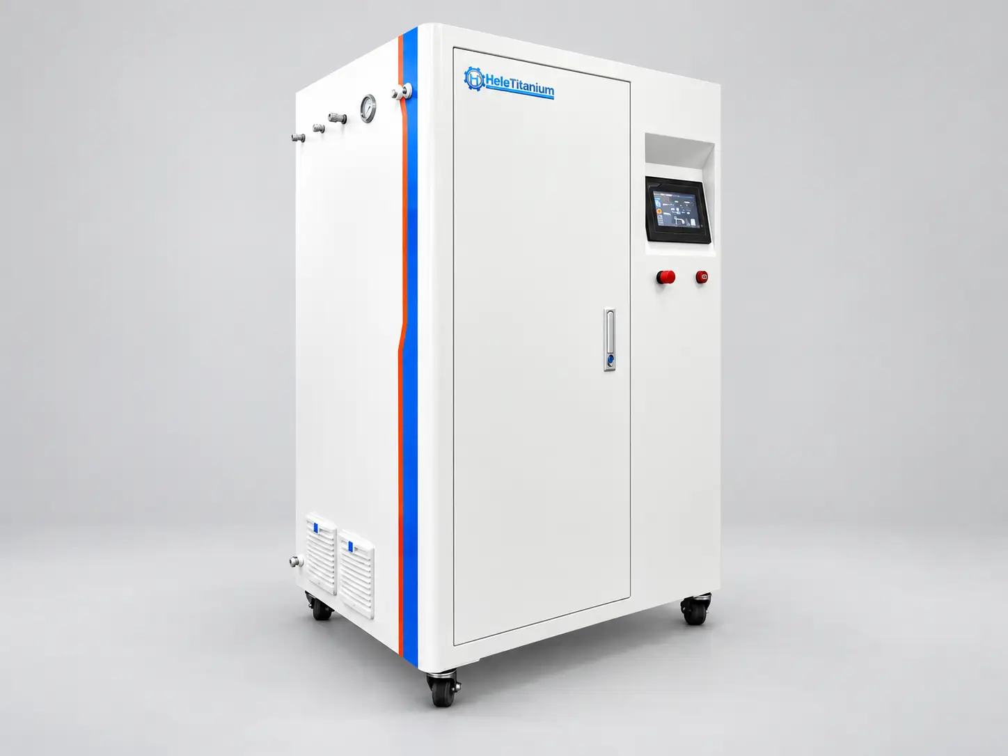
Industrial PEM electrolyzer system for on-site process hydrogen

Industrial process gas

On-site supply for chemical, metallurgical, electronics and general manufacturing duty, where concurrent peak demand and uptime drive the design.
Compact PEM electrolyzer supplying hydrogen for CVD diamond growth

CVD & diamond growth

Hydrogen supply for MPCVD and hot-filament reactors, where gas quality and pressure stability influence growth conditions and film quality.
PEM electrolysis and hydrogen storage demonstration system for teaching and research

Research & teaching

Test racks, single-channel platforms and demonstration systems for laboratories, universities and training facilities.
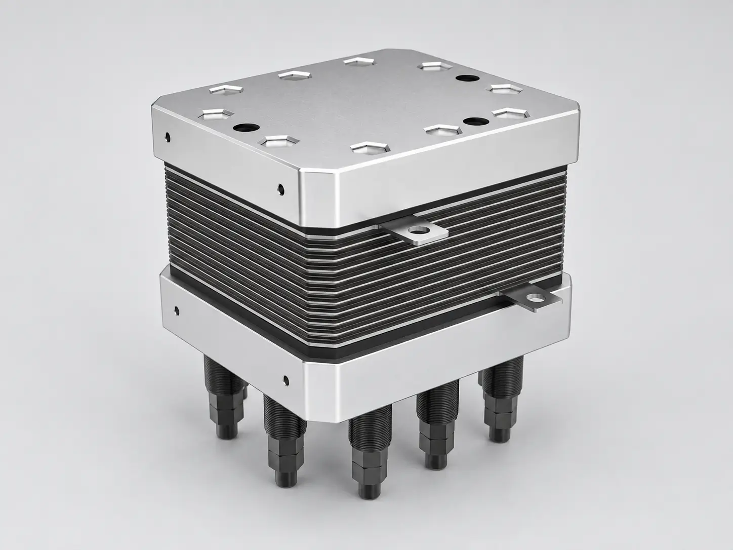
PEM electrolyzer stack for OEM integration

OEM & system integration

Stacks and sub-assemblies for integrators building their own hydrogen systems, with interfaces agreed against the receiving equipment.
Containerised PEM electrolyzer for renewable and remote-site hydrogen production

Renewable energy integration

Sizing and integration against solar, wind and hybrid input — including the ramp, minimum-load and cycling parameters that decide stack life.
High-capacity PEM electrolyzer supplying green hydrogen for chemical feedstock and storage

Chemicals & storage

Hydrogen for hydrogenation, methanol and ammonia feed, and storage-coupled operation — specified at the battery limit and against the offtake contract.
Reference data

Application map: duty, capacity and packaging

Reference mapping for configuration review. Series and packaging are confirmed against your own demand profile, gas quality requirement and site conditions.
Application Typical capacity band Packaging What usually sets the design
Laboratory & analytical
Instrument-specific flow; confirm reference conditions
Compact cabinet, bench or under-bench
Instrument gas quality and point-of-use limits
Pilot & small industrial
0.5–1 Nm³/h
Compact skid
Load profile and future expansion
Industrial skid
1–10 Nm³/h
Skid with monitoring
Concurrent peak demand and pressure stability
Plant-scale production
10–50 Nm³/h
Multi-module
Availability target and redundancy class
Large industrial / Power-to-X
50–200 Nm³/h
Containerised, scalable
Power profile, footprint and phase plan
Process & integration

Understand the equipment pathway

01
Feed water
Deionised water to the quality the PEM module requires.
02
PEM generation
On-site electrolysis; no stored electrolyte inventory.
03
Gas-liquid separation
Removes entrained water from the gas stream.
04
Drying & purification
Scope set by the moisture and impurity limits you specify.
05
Delivery
Pressure and quality defined at the point of use, with monitoring agreed.
PEM electrolyzer system integration workshop
System integration is carried out in-house, which is what makes non-standard configurations and interface requirements workable.
Buyer questions

Questions before specification

How do I choose between a laboratory and an industrial hydrogen system?

The split is set by gas demand and duty cycle, not by the label. Laboratory duty is defined by instrument flow, often tens of millilitres to a few litres per minute with intermittent operation. Industrial duty is defined by concurrent peak demand across a plant header, continuous operation and a stated availability target.
The series describe output range and packaging. Compact units cover low flows for laboratory and pilot duty, mid-range systems cover small industrial skids, and larger or containerised systems serve plant-scale and multi-module installations. Final selection is confirmed against your flow, pressure, purity and duty cycle.
No. The required gas quality is set by the receiving process or instrument, and it must be defined at the delivery point rather than at the generator outlet. Moisture and individual impurity limits, not a single headline percentage, are what determine the gas treatment scope.
Yes, provided the shared header is specified for the combined peak demand and the gas quality meets the most demanding consumer. Where consumers need different purity or pressure, separate branches or separate systems are usually more practical.
Each application page lists the reference configuration, and the datasheet requests show the equipment boundaries. The approved technical specification with the quotation defines the supplied scope.
Next step / configuration review

Tell us what the equipment needs to do

Send your application, gas demand and delivery requirements. Include the destination country and any procurement specification so the proposed scope can be reviewed against your project. A useful brief covers the four points below.

SUBMIT YOUR REQUEST