
Home / Applications / CVD Diamond

CVD & diamond growth

Hydrogen Supply for CVD Diamond Growth

One reactor is straightforward. A growth line is where supply design starts to matter: demand multiplies, gas quality has to hold at every reactor inlet, and a pressure dip when one reactor starts shows up as variation on the others.
PEM
No stored electrolyte inventory
99.999%
Hydrogen purity
By model
Delivery pressure
Modular
Single reactor to fleet
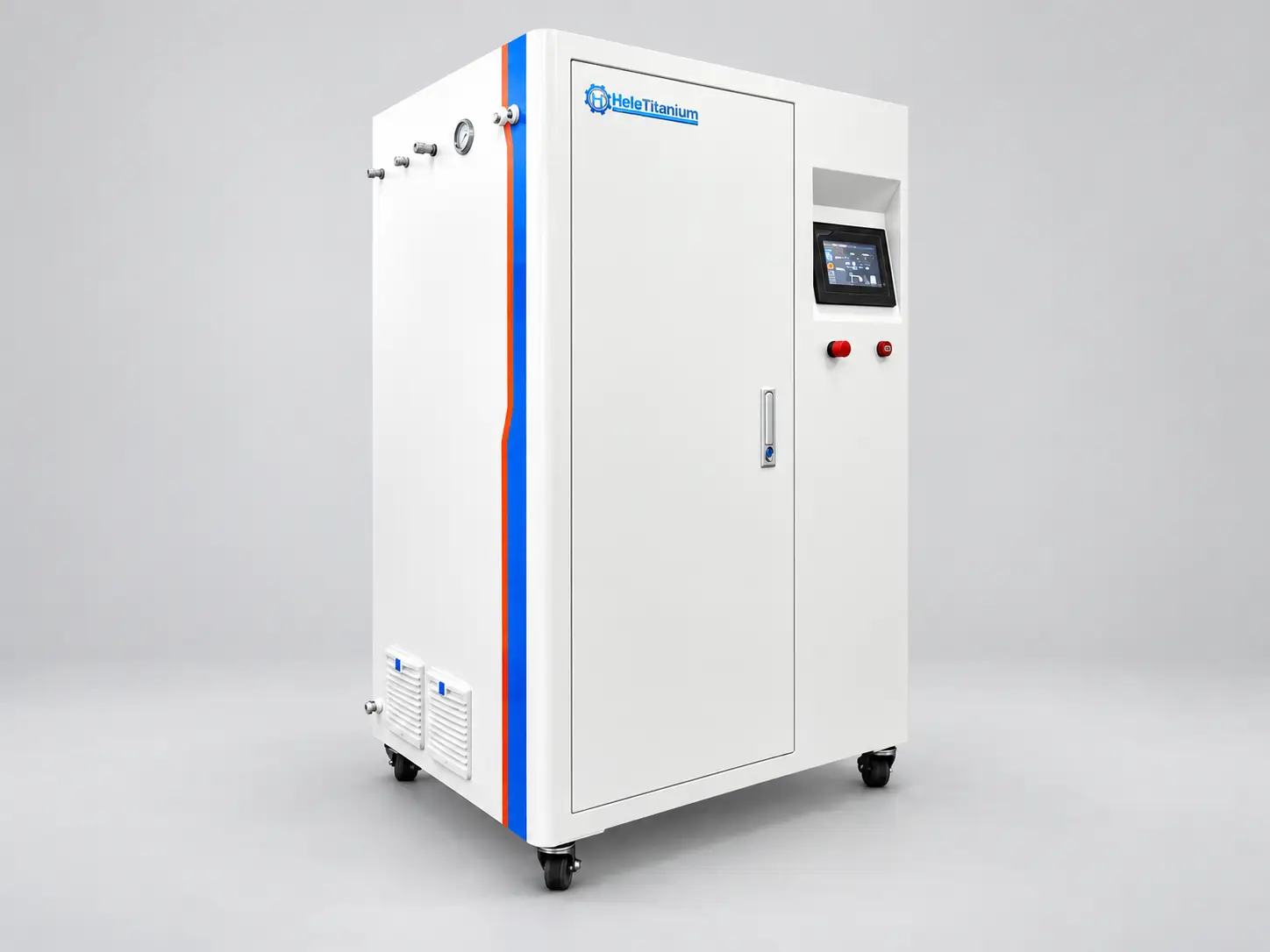
Compact PEM electrolyzer supplying hydrogen gas to a CVD diamond growth reactor
Reference configuration shown. Supplied equipment and appearance depend on the approved specification.
Project scope

Match the supply to your reactor line

Share the reactor count, maximum flow per reactor, simultaneous-use pattern, inlet pressure and impurity limits. The 0.5–200 Nm³/h system portfolio is a starting point for configuration review; a purity label alone does not establish reactor compatibility.
01 · Demand
Concurrent reactor flow, excluding design margin.
02 · Conditioning
Specify moisture, oxygen and other impurity limits.
03 · Distribution
Agree manifold, branch isolation and sampling locations.
04 · Backup
Review buffer and standby supply with the reactor supplier.
Purpose & value

What changes from one reactor to a growth line

Adding reactors does not simply multiply the flow. It changes which variables have to be controlled.

The supply becomes shared

With one reactor the generator is effectively dedicated. With several, every reactor start draws on the same header. A system sized on a single reactor causes a pressure dip across all of them the moment the next one begins.

Gas quality has to hold per reactor

Moisture, oxygen and nitrogen-containing species influence nucleation and film quality. A figure measured at the generator outlet does not describe what the fourth reactor actually receives.

Uptime becomes a yield variable

A generator stop interrupts every growth run in progress. Planned maintenance has to be reconciled with the growth schedule, or redundancy has to be designed in from the start.

Cylinder logistics stop scaling

Cylinder supply works at laboratory volume. As reactor count rises, changeovers, storage compliance and handling labour become the constraint before gas cost does.
Technical details

Reference specifications

Reference data for configuration review. The accepted quotation and approved technical specification define the supplied equipment.
Parameter Reference value Note
Technology
PEM water electrolysis
Deionised water feed; no liquid electrolyte inventory
Standard purity
99.999%
Confirm gas treatment, sampling point and impurity limits for the selected model
Delivery pressure
By model
Delivered pressure defined at the point of use
Gas treatment
Separation, drying, purification
Scope follows the impurity limits you specify
Control
PLC + HMI
Pressure, flow and temperature monitoring
Remote monitoring
TCP/IP
Available depending on configuration
Supply architecture
Central manifold or per-reactor
Selected against your independence requirement
Process & integration

Two supply architectures

Central generation with a distribution manifold

One generation system feeding several reactors through a manifold. Usually the lower cost per unit of capacity and the simpler arrangement to service. Requires the manifold, controls and utilities to be specified for the intended final reactor count, and per-branch quality and pressure monitoring to keep traceability.

Dedicated supply per reactor

An individual generation unit for each reactor. Isolates quality and pressure between reactors and allows one reactor to be serviced without touching the others. Higher cost per unit of capacity, and more equipment to maintain.
Containerised PEM electrolyzer configuration for multi-reactor hydrogen supply
Where the gas supply sits outside the reactor room, containerised configurations keep the footprint and the service access separate from the growth area.
Gas quality

Set the limits at the reactor inlet

Why each impurity class is controlled, and where the limit belongs. Set the actual values from your growth process and confirm them with the reactor supplier — not from a gas-system vendor’s generic table.
Impurity class Why it matters in diamond growth Where the limit belongs
Moisture (H₂O)
Influences plasma chemistry and film quality
Reactor inlet, after final purification
Oxygen (O₂)
Affects nucleation and growth chemistry
Reactor inlet
Nitrogen species
Influence growth behaviour and dopant effects
Reactor inlet, per your recipe
Hydrocarbons
Unintended carbon source for the growth chemistry
Reactor inlet
Particulates
Defect sources and chamber contamination
Filtration upstream of the reactor
If your recipe is confidential, give us the flow and gas-quality envelope only. Sizing can be done on that basis, and the detailed specification can be agreed under NDA.
Before you request a quote

What to have ready

  • Reactor type (MPCVD, hot-filament, other) and chamber pressure
  • Hydrogen flow per reactor, from your own recipe
  • Number of reactors operating today and in each later phase
  • Gas quality limits at the reactor inlet, from your growth process
  • Required pressure at the reactor inlet and tolerance
  • Concurrent-operation rule: which reactors may run together
  • Uptime requirement and planned maintenance window
  • Available footprint, utilities and whether the supply sits inside or outside the reactor area
Buyer questions

Questions before specification

What gas quality does CVD diamond growth require?

Diamond growth is sensitive to moisture, oxygen and nitrogen-containing species because they influence nucleation and film quality. The limits should be taken from your growth process and validated experimentally with the reactor supplier, and they must be specified at the reactor inlet rather than at the generator outlet.
Consumption is set by chamber pressure, gas mixture and reactor geometry, so the only reliable figure is the one from your own recipe. Because output ranges differ by an order of magnitude between laboratory and production reactors, sizing on a single reactor usually fails as soon as a second one is added.
Both architectures are used. A central generator with a distribution manifold is usually more economical per unit of capacity and simpler to service. Dedicated supply per reactor isolates quality and pressure between reactors. The choice follows how independent your growth processes need to be.
Flow or pressure fluctuation changes the plasma conditions and therefore growth rate, uniformity and film properties. Pressure stability, and preventing a dip when another reactor starts, are quality variables rather than utility variables.
Yes, if the manifold, controls and utilities are specified for the intended final reactor count when the first module is installed. Expanding later without that groundwork usually means rebuilding the gas distribution.

Next step / configuration review

Send your reactor specification

Tell us the reactor type, how many reactors you operate or plan to operate, and the flow and gas quality your recipe requires. Include the destination country and any procurement specification so the proposed scope can be reviewed against your project.
Continue your selection

Related equipment

SUBMIT YOUR REQUEST