
Home / PEM Electrolysis Technology Guide
Technology

PEM Electrolysis Technology: How It Works, and What to Specify

In one paragraph: deionised water is split at the anode into oxygen, protons and electrons; the protons cross a proton-exchange membrane to the cathode and recombine into hydrogen. Because the membrane carries the ionic current, there is no liquid electrolyte inventory — which is why PEM responds quickly to load changes and delivers high-purity gas with comparatively compact downstream treatment. What follows is what each of those statements means when you write a specification.
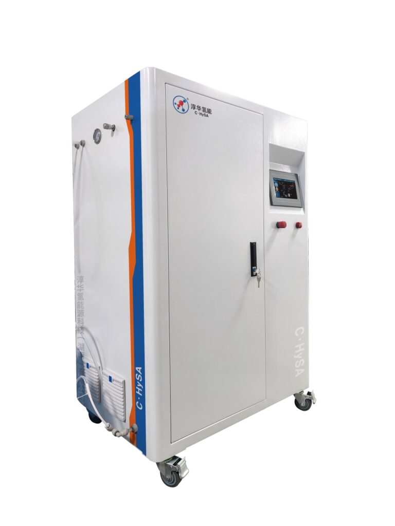
PEM water electrolyzer system illustrating proton exchange membrane hydrogen production
Reference configuration shown. Supplied equipment and appearance depend on the approved specification.
Fundamentals

Stack anatomy

01 · Water / anode
Water supplies the oxygen and protons involved in electrolysis.
02 · PEM
The membrane transports protons while separating the product gases.
03 · Cathode
Hydrogen is formed at the cathode.
04 · Balance of plant
Power conversion, water circulation and gas treatment support the stack.
Every parameter you later have to specify traces back to one of these four layers.

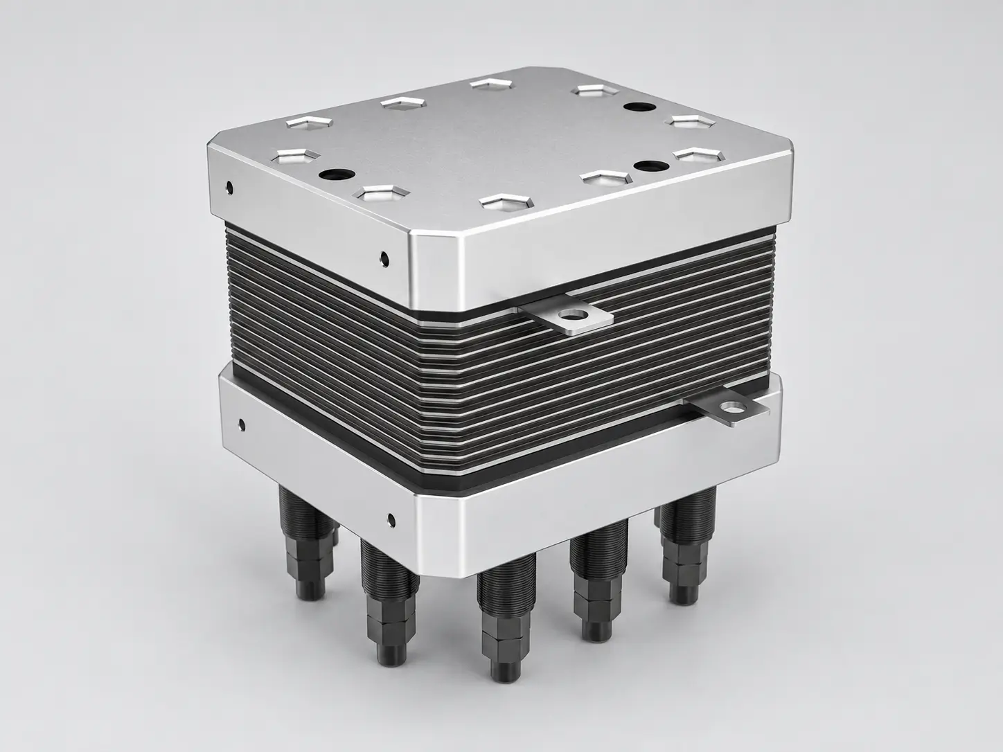
Membrane

The proton-conducting polymer. Thinner membranes conduct better but are more exposed to mechanical stress and cross-permeation; thickness is a design trade-off, not a free parameter. It sets the practical limits on pressure differential and load cycling.
Catalyst layers

Iridium-based at the anode, platinum-based at the cathode. Catalyst loading drives cost and durability at the same time — lowering loading to cut cost is what makes degradation and contamination sensitivity more relevant to you as a buyer.

Porous transport layers and bipolar plates

They distribute water and current and remove heat. Their material and coating decide corrosion behaviour and long-run contact resistance, which is a common reason nominally identical stacks diverge in service.

Balance of plant

Water treatment, gas-liquid separation, drying and purification, thermal management, power supply and controls. In a delivered system this is where most of the equipment scope and most of the integration risk sits.
PEM electrolyzer stack showing membrane, catalyst and bipolar plate assembly
Stack assembly. Stack specification sets the achievable turndown and pressure, but the delivered system behaviour is decided by the balance of plant around it.
Technology comparison

PEM vs alkaline vs AEM

Qualitative comparison for planning. Confirm the actual limits against the datasheet of the specific product you are offered — they differ by manufacturer.
Factor PEM Alkaline AEM
Response to load changes
Check the specified ramp and start-stop limits
Check validated operating limits for the model
Operation at part load
Wide range
More limited at low load
Improving, less field history
Gas quality with limited treatment
Verify measured outlet impurities and treatment scope
Footprint at smaller scale
Compact
Larger balance of plant
Compact
Capital cost at large scale
Compare installed cost and operating assumptions
Request a commercial quotation at the same scope
Dominant practical constraint
Catalyst and membrane cost
Response speed and gas treatment
Commercial maturity and supply chain
Rule of thumb. Compare validated load curves, gas-treatment scope and total installed cost at the same duty. Technology labels alone do not establish a performance or cost advantage.
Efficiency

What kWh per Nm³ actually means

Energy consumption is quoted in several ways, and comparing them without aligning the boundary is a common source of confusion.
Planning reference values. Treat as an estimate for sizing conversations, not as a guarantee — actual consumption depends on current density, pressure, temperature, water quality and part-load operation, and must be confirmed against measured data for the configuration offered.
Boundary Reference value What is included
Stack
≈ 4.5 kWh / Nm³
Electrolysis reaction only
Balance of plant
≈ 0.5 kWh / Nm³
Water treatment, cooling, controls, auxiliaries
System, at rated load
≈ 5 kWh / Nm³
Stack + balance of plant
System, part load
Use the measured load curve
Stack efficiency and auxiliary consumption vary with load; net system consumption is configuration-dependent
Durability

Degradation mechanisms you can influence

Membrane thinning and pinholing

Driven by mechanical stress and chemical attack. Aggravated by wide, frequent pressure or load swings. Controllable through ramp limits agreed at specification.

Catalyst dissolution and migration

Accelerated by high potential excursions and by start-stop cycling. Relevant if your duty profile includes frequent shutdowns rather than steady running.

Contamination

From feed water quality and from system components upstream. This is the mechanism most directly under the operator’s control — and the reason water specification is part of the equipment specification.
In practice, expected stack life is a function of your load profile as much as of the product. Ask a supplier for the duty profile their life figure was established under, and compare it with your own.
Specification

What to put in the specification

  • Output range and required turndown
  • Gas quality defined at the delivery point, not the generator outlet
  • Output pressure and the pressure required at each consumer
  • Duty cycle and load profile, including start-stop frequency
  • Energy consumption and the boundary it is measured over
  • Feed water specification and treatment scope
  • Ambient conditions, altitude, cooling and electrical supply
  • Control, monitoring and remote access scope
  • Safety features and applicable standards
  • Factory acceptance test scope, documentation and spares
Buyer questions

Questions before specification

How does PEM water electrolysis work?

Deionised water is fed to the anode side, where it is split into oxygen, protons and electrons. The protons cross a proton-exchange membrane to the cathode, where they recombine into hydrogen gas. Because the membrane carries the ionic current, no liquid electrolyte inventory is required.
This guide uses an illustrative split of 4.5 kWh per Nm³ for the stack plus 0.5 for auxiliaries, totalling 5 kWh per Nm³. This is an example assumption, not a measured value for every model. Actual consumption depends on current density, pressure, temperature, water quality and part-load operation, so it must be confirmed against measured data for the specific configuration.
Compare the specific models at the same output, gas quality, pressure, load profile and equipment boundary. Check documented ramp limits, treatment requirements, installed cost and energy consumption rather than assuming a fixed ranking by technology.
The main mechanisms are membrane thinning and pinholing, catalyst dissolution and migration, and contamination from feed water or system components. Load cycling accelerates mechanical stress. Feed water quality, ramp limits and avoiding excessive start-stop cycling are the controllable factors.
Output range and turndown, gas quality defined at the delivery point, output pressure, duty cycle and load profile, ambient and utility conditions, energy consumption boundary, control and monitoring scope, safety and standards compliance, factory acceptance test scope and documentation.
Next step / configuration review

Ask us to review your specification

Send your duty profile and the parameters above, and we will review the configuration against them. Include the destination country and any procurement specification so the proposed scope can be checked against your project.
Project scope

Technical references and review basis

DOE: hydrogen production by electrolysis explains the electrolysis process; DOE: PEM stack and system technical targets distinguishes stack and system metrics. Industry targets are not product guarantees.
Prepared by Hele Titanium Hydrogen. Updated 4 October 2026. Model-specific values require technical confirmation.

SUBMIT YOUR REQUEST